
| | Home | Fine Pitch Probes | FAQ | Custom Fixtures and Contact Us | Register | ||
|
|
|
|
Here are our answers to some frequently asked questions about AlphaTest Corporation's MicroHELIX pogo pin probes and test fixtures that offer unparalleled performance, accuracy, and reliability. Our durable MicroHELIX probes have proven to last hundreds of thousands of test cycles, providing long-lasting, accurate, and reliable testing capabilities. For information about custom test fixtures and sockets please click on our Custom Fixtures and Contact Us tab.
RF Applications require a temporary test connection which is electrically invisible or at least electrically nonintrusive. Ideally the contact would have compliance and zero length. Since that is itself a contradiction, the next best combination is just enough compliance and little length since length introduces some series inductance, capacitance, resistance and some signal delay. That makes our small diameter and short length test probes the perfect choice for two reasons. First, package configurations often require 0,5 mm (or closer) spacing of electrical test contacts. Second, at the rf frequencies involved in testing wireless technology (such as Bluetooth® technology) and other telecommunication, radar, and sensor devices the signals would be attenuated and/or distorted by conventional test probes. See TN0026 for additional information about the characterization of rf test probes.
| Probe Series: | S200 | S300 | S400 | S500 | ||||
|---|---|---|---|---|---|---|---|---|
| microns | (inches) | microns | (inches) | microns | (inches) | microns | (inches) | |
| Probe Diameters: | 200 | (0.008) | 300 | (0.012) | 400 | (0.016) | 500 | (0.020) |
| Minimum Centers: | 254 | (0.010) | 363 | (0.0143) | 477 | (0.0188) | 592 | (0.023) |
| Recommended Centers: | 279 | (0.011) | 390 | (0.015) | 500 | (0.020) | 617 | (0.024) |
| Minimum wall thickness: | 13 | (0.0005) | 20 | (0.0008) | 20 | (0.0008) | 20 | (0.0008) |
| Group ID | Diameter | |
|---|---|---|
| S500 Series | 500 micron | (0.020") |
| S400 Series | 400 micron | (0.016") |
| S300 Series | 300 micron | (0.012") |
| S200 Series | 200 micron | (0.008") |
| S500 Series | Body: μm (inches) | Plunger: μm (") | i/o Pin: μm(") | Overall: mm (") | ||||
|---|---|---|---|---|---|---|---|---|
| S500*6350-P1 Group | 6350 | (0.250) | 1900 | (0.075) | 8,25 | (0.325) | ||
| S500*6350-P2 Group | 6350 | (0.250) | 1900 | (0.075) | 1900 | (0.075) | 10,15 | (0.400) |
| S500*5500-P2 Group | 5500 | (0.217) | 1300 | (0.051) | 1300 | (0.051) | 8,10 | (0.319) |
| S500*4500-P2 Group | 4500 | (0.177) | 1300 | (0.051) | 1300 | (0.051) | 7,10 | (0.280) |
| S500*3800-P1 Group | 3800 | (0.150) | 1300 | (0.051) | 5,10 | (0.201) | ||
| S500*3800-P2 Group | 3800 | (0.150) | 1300 | (0.051) | 1300 | (0.051) | 6,40 | (0.252) |
| S500*3000-P1 Group | 3000 | (0.150) | 800 | (0.031) | 3,80 | (0.181) | ||
| S500*2440-P1 Group | 2440 | (0.096) | 610 | (0.024) | 3,05 | (0.120) | ||
| S400 Series | Body: μm (inches) | Plunger: μm (") | i/o Pin: μm(") | Overall: mm (") | ||||
|---|---|---|---|---|---|---|---|---|
| S400*6350-P1 Group | 6350 | (0.250) | 1900 | (0.075) | 8,25 | (0.325) | ||
| S400*6350-P2 Group | 6350 | (0.250) | 1900 | (0.075) | 1900 | (0.075) | 10,15 | (0.400) |
| S400*4500-P2 Group | 4500 | (0.177) | 1300 | (0.051) | 1300 | (0.051) | 7,10 | (0.280) |
| S400*3800-P1 Group | 3800 | (0.150) | 1300 | (0.051) | 5,10 | (0.201) | ||
| S400*3800-P2 Group | 3800 | (0.150) | 1300 | (0.051) | 1300 | (0.051) | 6,40 | (0.252) |
| S400*2440-P1 Group | 2440 | (0.096) | 610 | (0.024) | 3,05 | (0.120) | ||
| S300 Series | Body: μm (inches) | Plunger: μm (") | i/o Pin: μm(") | Overall: mm (") | ||||
|---|---|---|---|---|---|---|---|---|
| S300*3800-P1 Group | 3800 | (0.150) | 1300 | (0.051) | 5,10 | (0.201) | ||
| S300*2300-P1 Group | 2300 | (0.091) | 1000 | (0.039) | 3,30 | (0.130) | ||
| S300*2050-P1 Group | 2050 | (0.081) | 450 | (0.018) | 2,66 | (0.105) | ||
| S200 Series | Body: µm (inches) | Plunger: µm (") | i/o Pin: µm (") | Overall: mm (") | ||||
|---|---|---|---|---|---|---|---|---|
| S200*3800-P1 Group | 3800 | (0.150) | 1300 | (0.051) | 5,10 | (0.201) | ||
| S200*2300-P1 Group | 2300 | (0.091) | 1000 | (0.039) | 3,30 | (0.130) | ||
| S200*2300-P2 Group | 2300 | (0.091) | 1000 | (0.039) | 1000 | (0.039) | 4,30 | (0.169) |
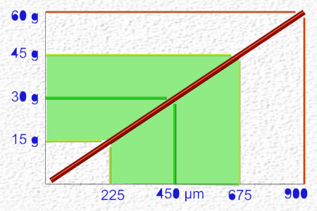
| Example: Drill cutting-speed vs Drill Size using 10,000 rpm cutting-speed in units/time = PI*(Dia in units)*(rpm)/(60 sec/min) |
||||||
|---|---|---|---|---|---|---|
| Drill Size | Cutting Speed | Application | ||||
| microns | inches | mm/sec | inches/sec | guide-hole for: | ||
| #74 | 572 | (0.0225) | 300 | (11.8) | S500 probe body | |
| 1/64" | 397 | (0.0156) | 208 | (8.2) | S500 plunger | i/o pin | |
| #77 | 457 | (0.018) | 239 | (9.4) | S400 probe body | |
| #80 | 343 | (0.0135) | 180 | (7.1) | S400 plunger | i/o pin | |
| S300 probe body | ||||||
| #88 | 240 | (0.0955) | 126 | (5.0) | S300 plunger | i/o pin | |
| S200 probe body | ||||||
| #96 | 160 | (0.0063) | 84 | (3.3) | S200 plunger | i/o pin | |
| Lead (Pb) | Polybrominated Diphenyl Ethers (PBDE) | |
| Mercury (Hg) | Bis(2-ethylhexyl)phthalate (DEHP) | |
| Cadmium (Cd) | Benzyl Butyl Phthalate (BBP) | |
| Hexavalent Chromium (Cr VI) | Dibutyl Phthalate (DBP) | |
| Polybrominated Biphenyls (PBB) | Diisobutyl Phthalate (DIBP) | |
NCAIS code 334515 - Instrument Manufacturing for Measuring and Testing Electricity and Electrical Signals
SIC code 3825 - Instruments for Measuring and Testing of Electricity and Electrical Signals.
- Or call us at 360 462-0201 during regular business hours: Monday-Thursday, 8 a.m.-5 p.m. and Friday, 8 a.m. to noon.
- Or visit our Register page and leave a message.
| AlphaTest Corporation | 261 W Business Park Loop | Shelton, WA 98584 | 360-462-0201 | info@alphatest.com | | Home | Fine Pitch Probes | FAQ | Custom Fixtures and Contact Us | Register |